


The Author
All text and illustrations on this website are copyright.
LATHE BACK STOP
A useful accessory for the Myford ML7B
Many times it is necessary to face off a thin piece in the lathe and it is difficult to hold these straight in the chuck. Also it is often difficult to machine several parts to identical lengths.
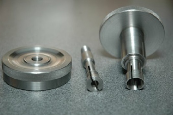
This lathe backstop fits in the back of the mandrel and the 1/4" bar is supported by a taper support fitted into the 2MT mandrel nose. The entire unit is shown assembled with some spare tips. It now only remains to find a suitable box in which to keep the bits tidy and without rust.
I shall probably have to drink some wine from a wooden wine box !! - all in the course of duty.
The original design came from Model Engineer's Workshop Issue No. 10 and as originally made and illustrated below, Tightening the hand wheel, both clamped the unit into the mandrel and also clamped the stop bar into the backstop unit.The problem with this was that the action of clamping the backstop, withdrew the backstop slightly, thus destroying the setting of the backstop.
The original backstop consisted of three pieces, each made from free cutting mild steel. The centre piece was split and fitted inside the main body of the item, which was also split at at the inner end. The end of the centre piece was threaded 40 T.P.I. and the large hand wheel screwed on to it.
Thus by tightening the hand wheel, the centre piece was drawn into the main body causing the centre piece to contract, gripping the bar, and causing the main body to expand to grip the inside of the lathe mandrel.
Both Harold Hall who designed the original, and I felt that the unit needed to be modified, but I did nothing about it until Harold Hall issued an improved design in MEW issue 165 and I then modified my unit.
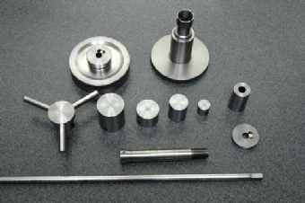
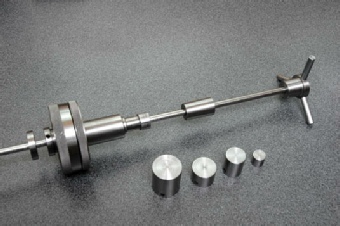
The parts of the revised backstop are shown below together with four end stops and a spider for use when turning thin rings or washers.
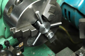
I created a clamping ring to clamp the stop rod and recessed this into the original tightening handle, fixing it to the handle with epoxy resin. A new un-split centre piece was made so that the backstop now only tightened into the bore of the mandrel, leaving the stop rod free to be adjusted and clamped with the clamping ring. The small pin stops it from rotating. The other disc is a setting ring which can be moved on the stop rod and clamped to it by a brass pad in order to facilitate setting the back stop to a measured position. At the top of the page you will see the unit in position on the lathe with the setting ring having been used to withdraw the stop rod by about 10 mm.
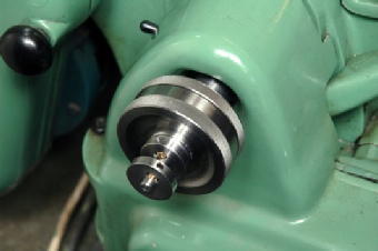
Finished Back Stop Fitted in the Outer End of the Mandrel
The New Backstop Set up with the Spider and Showing Alternative Tips
The Original Backstop Dismantled to Show The Three Piece Construction
The Parts of the New Backstop Dismantled to Show The Revised Construction
The New Backstop Set up with the Spider to Support a Thin Ring Whilst Turning