The Author
All text and illustrations on this website are copyright.
PILLAR TOOL
A Pillar Tool Made From Pipe Fittings

Designing by what is to hand
I had been thinking for some time of making a pillar tool as designed by George Thomas and available in kit form from Hemingway.
My problem was however, that I had always considered this to be a little on the small side for my requirements. I already had a 9" (228 mm) diameter lathe faceplate that had been given to me and which I had screw-cut to fit my Myford ML Super7B. I thought it would be ideal if this could double as a pillar tool table. I also had a motorised sensitive drilling head which had been adapted from a very broken cloth drill - used in the clothing industry. Unfortunately both of these items would require the tapping arms to have a reach of 5½" (140 mm) between centres as opposed to the George Thomas design which has a reach of 3½" (89 mm) between centres.
I do like the casting look rather than a machine that is obviously made up from plate and steel bars.I looked at a cast "Steam Tee" in a box of steam pipe fittings at work and I considered that two of these could be utilised to make an arm for a tapping tool / pillar tool.
The baseplate was rescued from a skip in keeping with the design philosophy for this project.
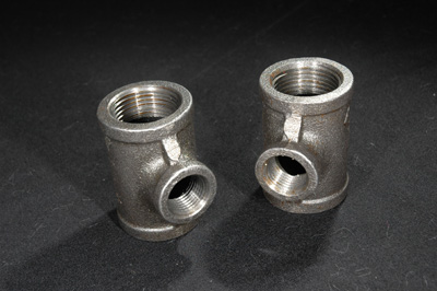
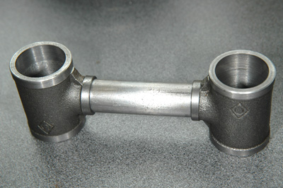
The 1" x 1/2" tees that inspired this project are shown below
Pillar Tool With Tapping Arm and Sensitive Drill Head
I started by, in effect, making a solid "casting" by boring the tees and filling them with steel, then boring the resulting arm to fit on the pillar. I considered that the best plan was to make the parts a good push fit and to Araldite (slow 2 part epoxy) the whole thing together. As the clamping arrangement was to be of the type which embodies a sliding brass cotter to press on the pillar, it was necessary to ensure that the inside of the tee was completely filled with steel, so that the clamping arrangement was not situated in a void.
I wasn't sure whether this construction would be rigid enough but in practice it feels to be built like the proverbial "brick outhouse".
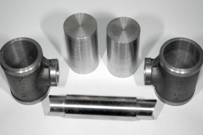
Steam Tees Ready To Start Making The Arms
The Bored out Tees Ready to be Filled With Steel
The Parts of the Arm Before Assembly
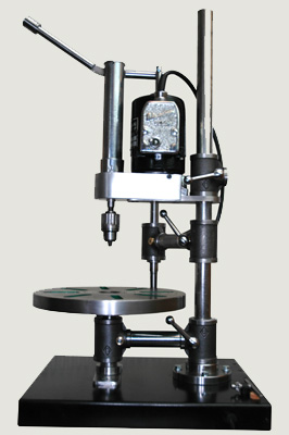
The Tapping tool itself, slides in a 1" sleeve. The vertical rotating shaft is 5/8" silver steel into which I fixed the body of a No.142 Eclipse tap wrench. This will hold all taps from 12BA to 7mm which covers most of the sizes that I regularly use. I stretched an "O" ring round the shaft and this jams into a taper at the top of the bore, thus stopping the shaft from dropping and breaking the tap. The O ring can be rolled up or down to adjust.
The lathe faceplate fits on a boss screwed to match my lathe and thus takes my lathe chucks when required.
The sensitive drilling attachment was originally a broken cloth drill which I repaired and then added the drilling spindle, feed handle and chuck. It is suitable for high speed drilling of holes up to about 5/32" or 4mm The original device just rotated a needle for drilling pocket positioning holes on garments.
The Tool in Tapping Mode
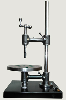
The Tapping Head Swung to One Side and Drilling Head Fitted