


The Author
All text and illustrations on this website are copyright.
WORKSHOP SPINDLE
A useful Spindle for Milling or Grinding
Milling Spindle Suitable for the Cross Slide of my Myford ML7B
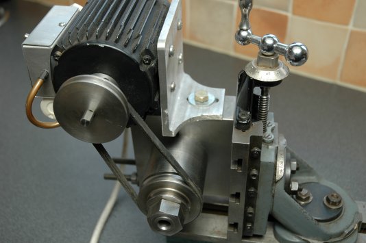
Drive Arrangement
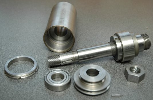
The Spindle Parts Before Assembly and Before Boring 2MT
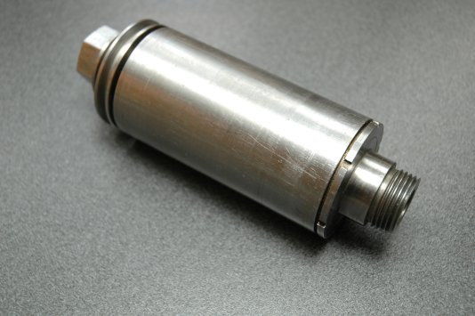
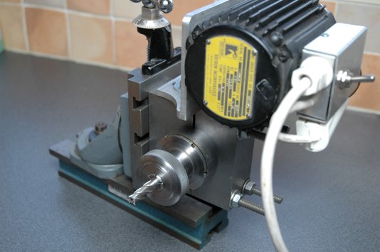
Basic Spindle Assembled
This useful lathe accessory is based upon a spindle from the Nexus Book "Spindles" The spindle also forms the main grinding spindle in my tool and cutter grinder illustrated on this website.
In the configuration here the spindle is normally mounted on either the cross slide or the vertical slide of my lathe using a split steel block to clamp the spindle and to hold the motor mounting bracket. The spindle has a 2MT bore and a Myford nose, therefore it will take Myford Collets (home made in my case) which have a very short overhang - essential if you are milling flats on a bar held in the lathe chuck.
The mounting block was made by clamping it onto the lathe cross slide, boring the hole to fit the spindle and then splitting the block to clamp the spindle tight. The block is split exactly on the centre of the bore. By this method I can be sure that the spindle is held exactly at centre height if using it as a drill from the cross slide.
The spindle is the basic spindle from the book, but is modified slightly to take a double angle bearing at the front.
The "basic" spindle was chosen as it had the Myford nose and a 2MT bore which makes it far more adaptable than the majority of light milling spindles. The drive is by small v belt from a sewing machine using a two step pulley.
The spindle itself has proved very robust and accurate. However the large nut to hold the drive pulley in position looks most incongruous to my eyes. It was constructed exactly as drawn in the book, but I intend to replace it with something that looks more "engineered" when it is rotating at 4,500 RPM.
Construction required some careful turning, but caused no great problems. The most demanding part was cutting the internal thread on the body end where the closing bush screws into the body (right end in the bottom photo) The six slots are to allow a "C" spanner to tighten up the closing bush on to the main bearing.
The parts of the spindle are illustrated here before assembly. The last thing done to the spindle was boring the 2MT socket. This is because it was bored using the spindle itself. After assembly the spindle was driven by the lathe, the socket was bored and then finished with a 2MT reamer. this ensured absolute concentricity.
I made the body of the spindle holder from an old roller from a scrapped machine. The two step pulley allows a change of speed, but is usually driven at the lower speed unless undertaking internal grinding.
The only bought parts are the bearings - which were a substantial price, but this device has really earned it's keep in the workshop.