

All text and illustrations on this website are copyright.

MANDREL HANDLE
For Myford ML7B
There are many occasions where it is sensible to power the lathe by hand, - the most frequent of these is when screwcutting an internal blind hole. Do this under power at your peril !!
There have been many designs published for lathe mandrel handles, some of them with complicated mechanisms enabling the handle to be made loose on the shaft in case the power to the lathe is inadvertently switched on, causing the handle to thrash about dangerously.
The handle shown here is perfectly balanced and therefore will spin without vibration should the lathe be inadvertently started under power. It will of course still constitute a hazard.
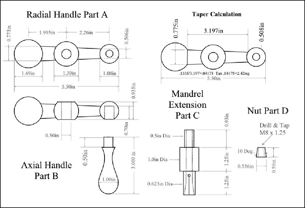
[ See Drawing ]
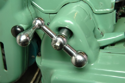
Mandrel Handle in Place on Myford ML7B Ready For Use
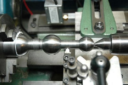
The idea for this started with an old cross slide handle from a large lathe. In making the radial arm of the handle, there are 3 "balls" to turn. I turned the small one first, ensuring that at just under 1" dia. it would go into the body of my 3 jaw chuck.
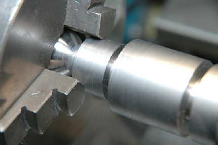
I left a 1" dia section on the bar for the chuck to hold the work, whilst turning the large ball and the middle ball.
The centre portion is the diameter of the centre ball and the end portion is the diameter of the large end ball.
Holding the Item for Turning the Large and Middle Balls
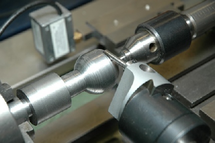
Using the Boring Head for Spherical Turning
I turned all 3 balls by the up-and-over method and in fact used my boring head mounted in a spindle on the vertical slide. This is a very effective way of making these and is shown in the photo below.
The large overhang is unimportant as the reaction thrust is horizontal.
As you will see from the photo, I put a small centre on each end which does not detract from the overall appearance.
The end of this ball was finished by withdrawing the tailstock rotating centre and using very light cuts.
Holding the handle for turning the tapered centre parts is difficult. First I made a steel tube which is a tight fit on the large ball. I then wrapped kitchen roll round the large ball and pushed it tight into the tube using the tailstock The grip was perfect, in fact they were difficult to separate afterwards.
The tapers were turned using a taper turning attachment and a round nosed tool. Then the assembly was transferred to the milling machine on a dividing head, again supporting with a tailstock, so that the flats could be milled on the centre part.
Finally the centre hole was drilled and reamed, and the blind hole for the axial part of the handle was also drilled and reamed.
Holding the Handle for Taper Turning

Turning the axial handle is not easy as it is all curves. I turned it to rough shape by rotating the top slide, and then did some turning using a round profile insert tool with careful twiddling of both cross slide and top slide knobs.
The most successful way was hand turning as shown in the photo, but it is necessary to use a long handled tool and to take careful, light cuts.
I made a central boss to fit the handle. The boss is split at the other end as shown in the photograph and is bored axially to fit a tapered plug (nut) that is drawn into the body of the boss by a bolt.
Thus the boss tightens on the inside of the lathe mandrel giving a friction drive to the lathe.
Turning the Axial Handle by Hand
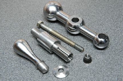
The Finished Parts Prior to Assembly
You may be able to see from the photograph that the conical nut carries a pin which runs in one of the slots cut into the boss. This stops the nut from spinning when the bolt is either tightened or loosened.
On occasions I have spun the mandrel at full speed with the handle in place when wanting to simply chamfer a shaft and not wishing to remove the handle. Not a trace of vibration, but make sure the workshop door is locked and no-one is with you. Better still, do it right and remove the handle.
The handle looks as though it simply grew on the Myford and is very tactile in use.
This handle was featured in Model Engineer no. 4341 in an article written by me.
See full construction details and plans on the Articles page.
